
FlangeTrak™: 8-Step Approach to 100% Leak Prevention
Written by: Mr. P. Gordon Britton, P.Eng, President @ INTEGRA Technologies
INTRODUCTION
The Oil, Gas, and Power industries are under constant pressure to work their plants at maximum design capabilities and for longer periods between shutdowns. The bolted joint is often regarded as the weak link in the plants pressure envelope.
Whether a subsea pipe flange, valve bonnet, heat exchanger or reactor manway, Joint Integrity relies not only on the mechanical design of the flange and its components, but also on its condition, maintenance and assembly. Plant personnel are looking for their processes to achieve Joint Integrity – leak free joints with reduced shutdown periods while increasing the time between shutdowns.
To achieve Joint Integrity a broader view of the bolted flange joint as a complex dynamic system must be adopted. A comprehensive process must be implemented to manage all the key elements of the bolted system, to enable the design potential of the bolted joint to be realized and helps in achieving continued leak-free operations.
The FlangeTrak™ 8 Step Leak Prevention Process has proven to be successful to help plants achieve Joint Integrity.
LEAKS ARE A THREAT TO PROFITS
Most industrial plants have a significant number of high-risk flanges that warrant plant wide concern. Generally these fall into one or more of the following:
- Flanges that CHRONICALLY Leak. Certain flanges are a continuing problem because of their tendency to leak in spite of ongoing efforts to fix them.
- Flanges that MUST NOT Leak. Certain flanges pose such potentially serious problems that they should never leak. Such leaks could cause:
a) physical injuries
b) unscheduled work stoppages –
production loss
c) damage to plant or equipment
d) late schedules
e) fires
f) regulatory and/or legal problems
g) environment concerns
LEAKS ARE PREVENTABLE
Problems resulting from leaks in flanges can range from local in severity, to plant-wide catastrophe. Although the range of negative results can vary widely, these high-risk leaks have one thing in common, ALL LEAKS ARE PREVENTABLE.
LEAKS ARE A CONTROL ISSUE
Leaks are a large industry issue. The Pressure Vessel Research Council (PVRC) performed a survey throughout North American industry and concluded that the average plant experiences 180 leaks per year. These range in severity from nuisance level to major shutdowns. A break down of the severity of these leaks is shown in Figure 1 PVRC – Industry Leak Study.

LEAKS ARE NOT ACCIDENTAL
The leak ratio pyramid is remarkably similar to the widely accepted industrial accident ratio pyramid. There is an industry culture that still prevails that leaking joints are normal and leaks cannot be prevented. It was not that long ago that similar views were held regarding health and safety that used to accept that some accidents cannot be prevented. Safety professionals now know that accidents can be prevented and the goal of Zero- Accidents is achievable.
In a manner similar to accident ratio statistics, there is a relationship between minor, serious and other dangerous events. All such events represent failure in control.
Leaks don’t happen by accident – they happen by design. Rather than being symptoms of product failure, leaks are generally evidence of failure in process control. When you fix the control process – you fix the leaks before they happen. As with Zero-Accidents, Zero-Leaks are also achievable.
FLANGED JOINTS ARE A CHALLENGE
Although static in appearance, flanged joints are actually a hotbed of physical activity. Joints are constantly being subjected to dramatic internal stresses caused by operating temperatures, pressures, and environmental conditions.
Each of these factors poses a constant threat to the critically close tolerances that the joint relies on for its sealing integrity.
These varying dynamics are continually challenging the joint through expansion and contraction of the flange housing, the bolts and the gasket itself. Each of these components reacts in its own unique way to these operational stresses. It is the failure to adequately understand and compensate for the complex inter-relationship of these dynamics that leads to joint failure.
Leaks are symptoms of a loss clamping pressure on the sealing element under operating conditions. This can be caused by a single factor – or a combination of factors.
Quality control factors that can negatively affect Joint Integrity include:
- Deviation or errors in bolt loadings during assembly procedures
- The flatness and/or texture of the flange face
- The creep relaxation of the gasket material
- Bolt metallurgy
THE IDEAL GASKET
In the selection of gaskets, the ideal gaskets should have the following properties:
- Compressibility – Gaskets should have sufficient compressibility to suit the style and surface finish of the flange, ensuring that all the imperfections will be filled with the gasket material.
- Resilience – Gaskets should have high resilience will enable the gasket to move with the dynamic loadings of the flange to maintain its seating stress.
- Creep Resistant – Gaskets should not deform after bolt up under varying load cycles of temperature and pressure or under a constant load at elevated temperatures.
The most difficult, often critical, property required of a gasket is its ability to resist creep during operation. In high-temperature services, the flanges will heat up at a faster rate than the bolts and under steady-state conditions will continue to be hotter than the bolts as a result of the thermal gradient. This results in a higher thermal expansion of the flanges with respect to the bolts, increasing the bolt load and concurrently the gasket stress. The gasket will then deform under the higher applied load during this cycle.
Most gaskets will deform permanently and will not rebound when the load cycle goes away with varying conditions. The permanent set or plastic deformation that occurred during the operation will cause loss of bolt load and concurrently loss of gasket stress. As gasket stress decreases leak rate increases.
IDEAL ASSEMBLY METHOD
The ideal assembly method involves the process that ensures that the desired bolt stress is achieved in the safest and most productive manner.
Control of the assembly bolt loads is critical to ensure the desired gasket stress and is achieved uniformly around the flange. Torquing with no other control device does not produce the desired level of control. This is illustrated in Figure 2.

Inaccuracies associated with torquing are a result of variations in stud/nut friction and cross talk. Cross talk is the effect of tightening one bolt at a time on adjacent bolts around the flange. As one bolt is tightened it tends to remove the load achieved in previously tightened bolts. Figure 2 shows the generally accepted wide deviations of bolt loads associated with torque. Controlling the bolt load is key to the assembly. Bolt loads that are too low will be susceptible to leakage in that area. Bolt loads that are too high can cause bolt yield and flange distortion unloading the gasket.
The desired result is to maximize the bolt load without yielding the bolts or flange. Multi-stud tensioning provides the accuracy demanded to ensure leak free joints. Additional benefits of multi-stud tensioning include improved safety and higher productivity.
Flanges are designed and intended to be leak-free. When flanges are properly specified, properly manufactured and properly installed they should be stronger and safer than the pipes they join. Flanges that leak are a symptom of process failure rather than product failure.
THE PROCESS OF JOINT INTEGRITY
There are over 120 variables that affect Flange Joint Integrity. By totally controlling every step in the scheduled flange maintenance process you are able to totally control the outcome. It is a seamless process of quality control that begins with focused engineering analysis and ends with 100% Leak Prevention.
The following briefly outlines the main elements of the FlangeTrak™ Eight Step Leak Prevention Process.
It is a system of Total Quality Management that is applied to each and every sealed joint that is included in the program.
FlangeTrak™ “8 Step” Leak Prevention Process
- Step 1: Client Consultation to define leak prevention objectives.
- Step 2: Detailed engineering analysis of all project elements
- Step 3: Establishment of detailed specification for each sealed assembly
- Step 4: Development of comprehensive procedures covering specific tooling and assembly
- Step 5: Assignment of competent, certified supervisors and operators
- Step 6: Verified proof of conformance at each significant step in the process
- Step 7: Extensive documentation and comprehensive final report
- Step 8: 100% Leak Prevention
For a full, detailed review of the activities completed in each step, please contact our team to discuss.
CASE STUDY
FlangeTrak™ – Eight Step Leak Prevention Process
To illustrate this process the following Case Study is reviewed:
OFFSHORE NATURAL GAS PLATFORM PASSES INDUSTRY’S TOUGHEST LEAK TEST WITH ZERO LEAKS
BACKGROUND
Working on the high seas is highly dangerous at the best of times. Combine that with the potentially explosive flammability of natural gas, and you have just two of the challenges facing Sable Offshore Energy in the design and construction of their new offshore platform complex. The Sable complex consists of three main platforms located 200km off the East Coast of Canada, to service one of the largest offshore natural gas fields in North America.
Their North Triumph natural gas processing platform is a key element in the complex. It is the initial upstream processing unit, which purges the natural gas of foreign matter, before
it is sent to other platforms for further processing.
Problems at North Triumph could not only cause serious safety and environmental concerns, they could also jeopardize production at all other stages of the operations.
For these and other reasons, Sable wanted to ensure that everything humanly possible would be done, to make sure the North Triumph platform would meet or exceed the utmost standards, in terms of safety, reliability, and environmental integrity.
Recognizing that flanged joints are typically the weakest link in the production process, they established an unprecedented objective for the construction of their North Triumph platform. Each and everyone of the more than 300 production flanges, must be guaranteed to be 100% Leak-Free – and to ensure this goal, they must be subjected to the most demanding testing available.
This case history is a brief overview of how Sable accomplished this seemingly impossible goal.
OVERVIEW
Sable Offshore Energy’s decision to achieve zero-leak operations on their new state-of-the-art North Triumph natural gas platform, led to INTEGRA Technologies being selected to do the flange servicing, based on the proven track record of their FlangeTrak™ leak-prevention services.
Nitrogen/Helium gas, a mixture similar to that used in the aerospace industry, was specified for the tests, which were carried out by experts from Halliburton Energy Services. It is believed this was the first time a natural gas platform built in North America had been subjected to such a rigorous test. Helium, being one of the smallest molecules, was used in the mix because it will rapidly show up through even the tiniest of leaks.
The North Triumph platform, was constructed in Halifax, as a joint venture by MM Industra/Brown & Root. Completed in mid- September 1999, the total system was then tested at pressures in excess of normal operating conditions. Given the severity of Nitrogen/Helium gas test, and the extremely intense test monitoring, re-work on approximately 20% of the flanges would normally be anticipated.
INTEGRA virtually eliminated all this costly and time consuming re-work – each of the more than 300 flanges INTEGRA had serviced, achieved Sable Offshore’s unprecedented goal – absolute, 100% ZERO-LEAKS!
The North Triumph platform, was then installed at the field and linked up with two other platforms, forming the largest off-shore natural gas production complex ever built in Canada. The complex was scheduled to be fully operational in November 1999.
Designed throughout to the highest safety and performance standards, the unmanned, fully automated platform, is expected to achieve optimum levels of productivity, and environmental integrity. Sable’s insistence on zero-leaks is further emphasized by the fact the North Triumph platform will operate without fire prevention systems that are mandatory on manned platforms.
INTEGRA’s FlangeTrak™ service is an exclusive, 8 step quality management process, that has earned INTEGRA a growing reputation as the ultimate supplier of zero-leak flange servicing technology. In addition to being safer and more overall cost-effective, FlangeTrak™ helps shorten total project schedules – a major concern for contractors who are faced with critical path penalties.
ABOUT THE FLANGETRAK™ 8 STEP PROCESS
As North America’s market leader in controlled bolting services, INTEGRA developed its 8 Step FlangeTrak™ process to respond to the Oil and Gas industry’s growing demands for optimal worker safety, certainty of production, and environmental integrity.
FlangeTrak™ is a total quality management process that ensures 100% Leak Prevention in the sealing of bolted assemblies such as pipe flanges, valves, vessel manways, and heat exchangers.
The ultimate objective of FlangeTrak™ is as follows:
Safety – ZERO ACCIDENTS
Quality – ZERO LEAKS
Productivity – ZERO DELAYS
Unlike other suppliers, which typically provide only piecemeal services, INTEGRA’s FlangeTrak™ service is a comprehensive process that professionally manages every one of the 8 steps involved in preventing leaks. As demonstrated on the North Triumph project, it is a seamless quality control program, that begins with focused engineering analysis, and ends with 100% Leak- Prevention.
100% Leak-Prevention requires superior performance at each the 8 steps in the process. INTEGRA’s achieves this outcome through superior experience, superior training and skills, superior methodology, and superior tooling. Proof of this expertise is the regular acceptance of the FlangeTrak™ process by INTEGRA’s ISO 9001 clients.
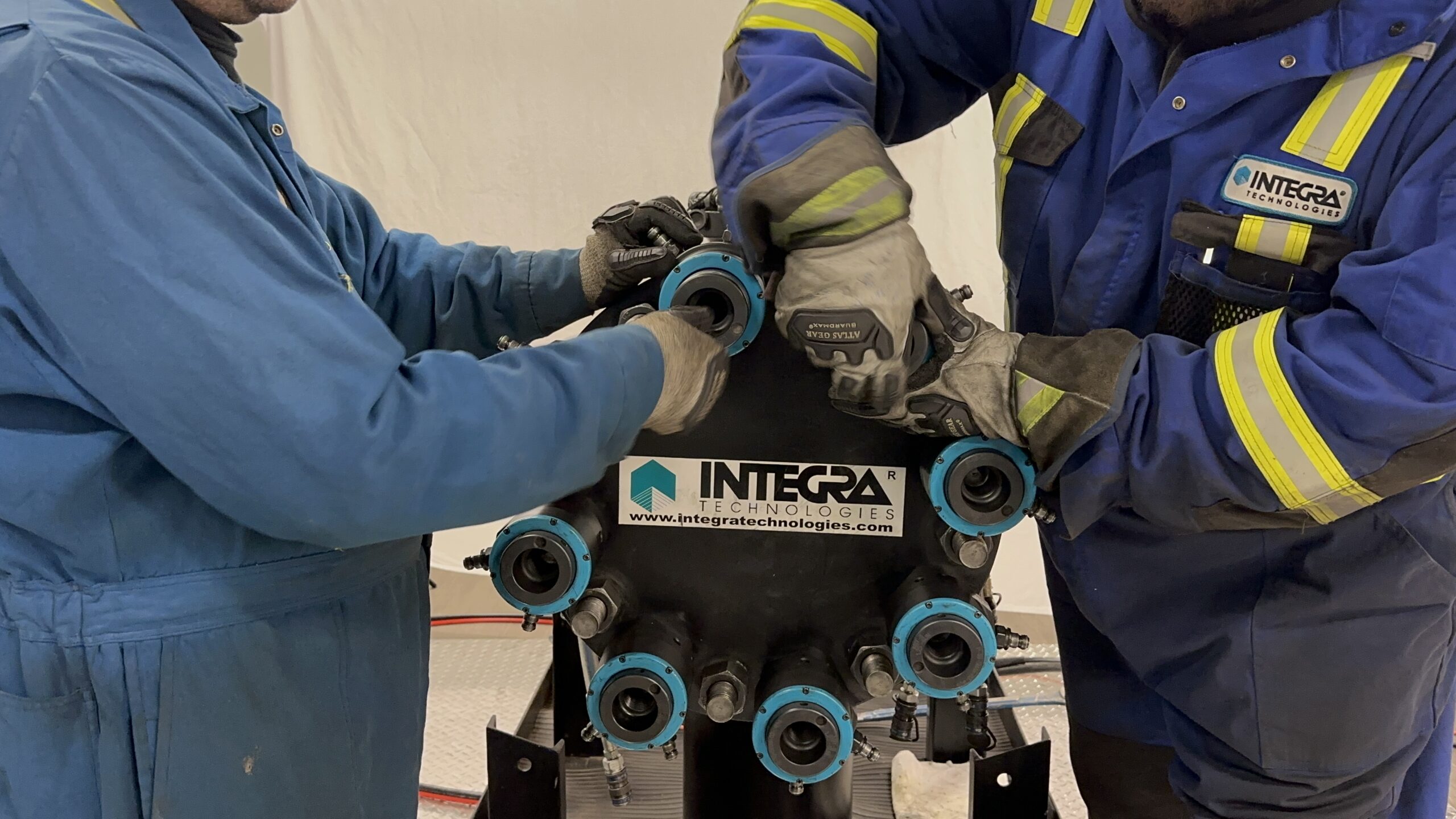
One example of INTEGRA’s best practices approach is their use of hydraulic multi-stud tensioning, which was used throughout the North Triumph project on all bolts in excess of 1 1/8” dia. By applying hydraulic power simultaneously to bolts on all sides of the flange housing, precise clamping pressure is evenly and accurately applied to the gasket and flange face in a single operation. Thus ensuring optimum leak-sealing in the fastest, safest way possible.
Every step in the FlangeTrak™ process is designed to meet or exceed design specifications. All work is extensively documented as proof of conformance, and a detailed computerized final report is provided which profiles the specifications and status of each and every flange involved in the project.
“FlangeTrak™ had proven itself long before the North Triumph project”, said Gordon Britton, President of INTEGRA Technologies, “but never before had we faced anything as challenging as a Nitrogen/Helium leak test. It just doesn’t get any tougher than that – and we passed the test with flying colors”.
And pass the test they did. As with INTEGRA’s other FlangeTrak™ projects, Sable Offshore’s North Triumph platform achieved its goal – zero-leaks on every one of the more than 300 flanges INTEGRA serviced. But a zero-leak outcome was only part of the package – in addition, there were zero accidents, zero environmental impacts, zero re-work required, and zero delays in critical path. All because of INTEGRA’s exclusive FlangeTrak™ process.
CONCLUSION
Leaks are a threat to profits, safety and the environment. This paper has reviewed the key elements to achieving Flange Joint Integrity to assure the leak-free integrity of the bolted flange joint. An integrated approach must be adopted to ensure the success of the process of Joint Integrity.
The goal of leak prevention is achievable and starts with the mindset of doing things right the first time.
REFERENCES
- J.R. Payne, “PVRC Flange Joint User Survey”, WRC Bulletin 306, July 1985
- John Bickford, “Introduction to the Design and Behavior of Bolted Joint:, Third Edition, Marcel Dekker Inc N.Y. N.Y. 1995